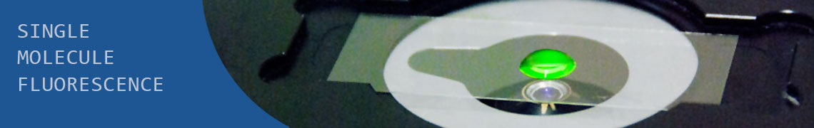
Setup for the irradiation of small liquid samples with high power LED light.
Wajih Al-Soufi, University of Santiago de Compostela, Facultad de Ciencias, 27002 Lugo, Spain wajih.al-soufi@usc.es, 2014We designed in cooperation with the group of Prof. José Luis Mascareñas and Prof. Eugenio Vázquez the following setup for the irradiation of liquid samples with high power LED light.
Photochemical reactions, cis-trans isomerizations, photolysis of caged compounds, etc. are preferably driven by light with narrow spectral bandwidth, high intensity and low heat output. High power LEDs are well suited and cost efficient solution. LEDs have long lifetimes, are easily controlled, and have constant and reproducible output.
The sample is placed in a standard 10mm2 cuvette in a sample holder and is irradiated by one to four LED units. The light from the LEDs is collimated by a plano-convex lens with short focal length in order to maximize irradiation power. In the case of one or two LED units mirrors can be placed in front of the opposite windows in order to reflect the transmitted light back into the sample.
The setup is straightforward and similar to commercially available equipment.
All parts can be purchased from Thorlabs, Inc.
The CAD drawings show the setup with all parts as delivered, without further modifications. However, in our real setup our machine shop introduced two small modifications:
- we added a M6 bore in the base plate in order to mount the post holder in the center of the plate. In the drawing we use a clamping fork, which does the same job.
- we widened the window bores of the cuvette holder to a diameter of 10mm in order to maximize the light input and the irradiated volume in the sample. This is optional.
CAD-Drawings:
Click on figures for higher resolution.
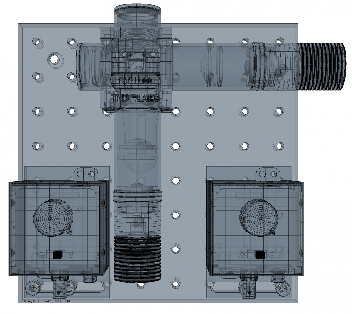
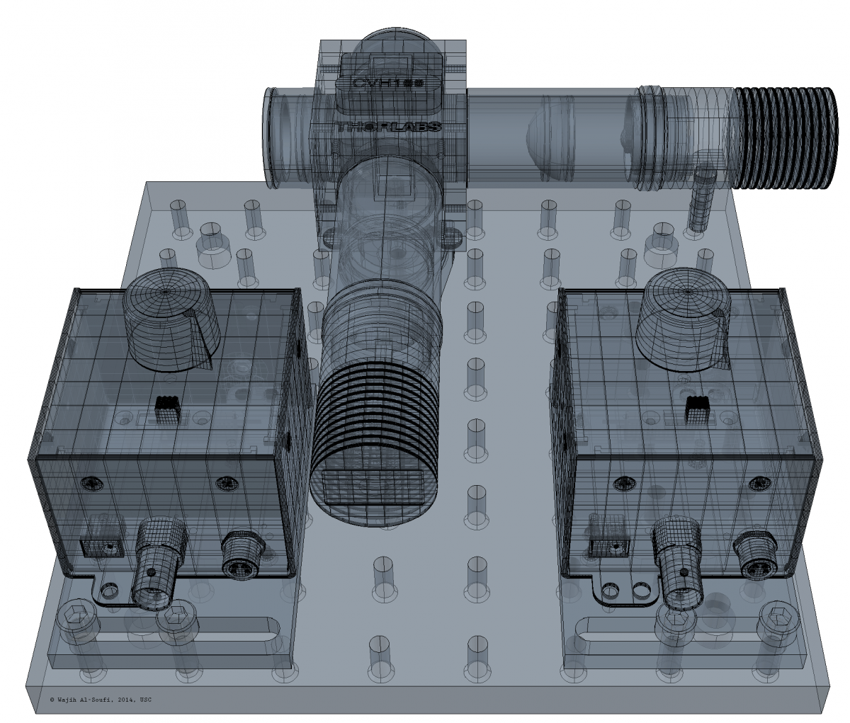
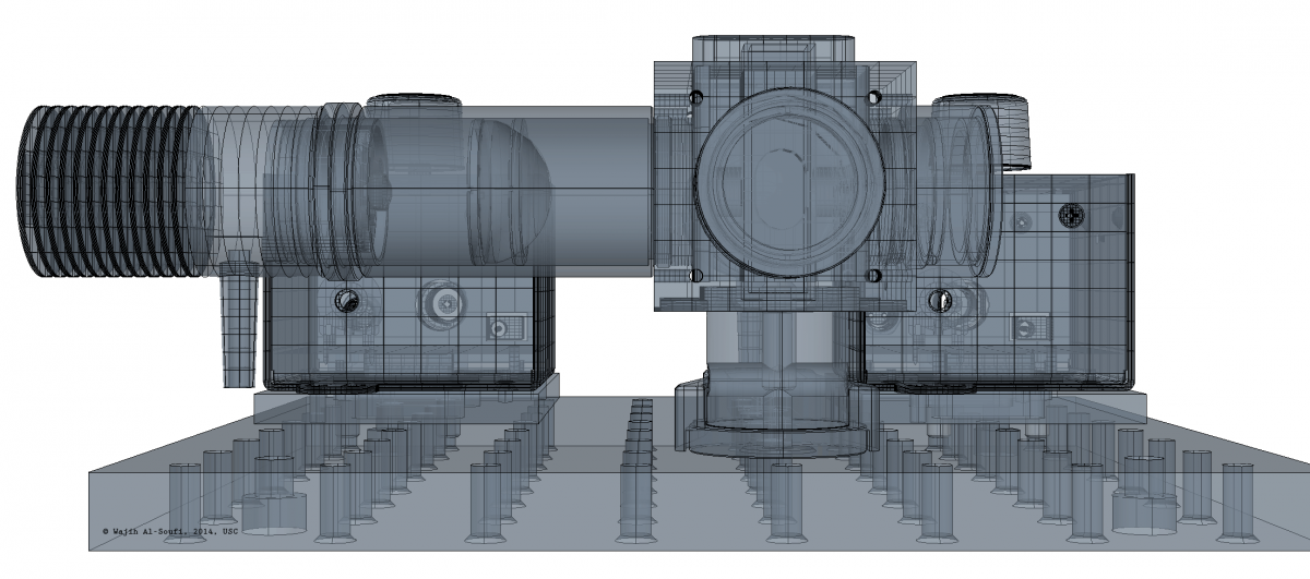
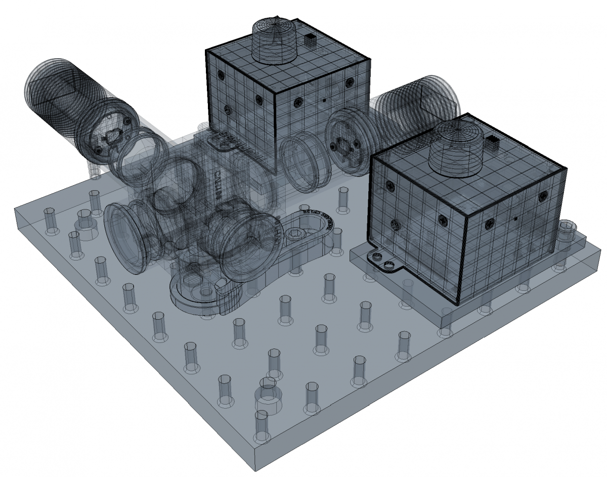
CAD-Drawings of the setup with illumination-module, power supplies and breadboard.
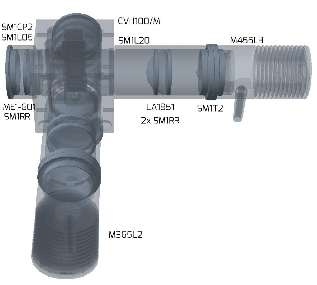
CAD-Drawing of the illumination-module with Thorlabs item numbers.
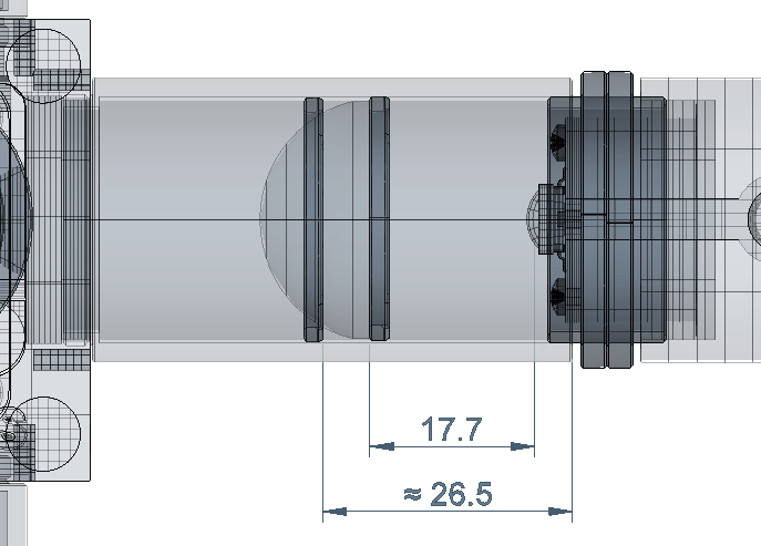
CAD-Drawing of the illumination-module with approximate distances in mm.
Images:
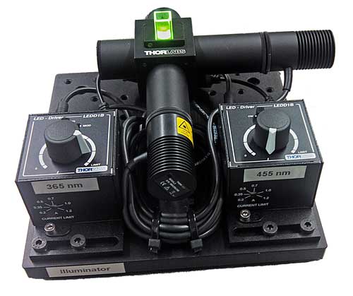
Complete setup with two LEDs. (Some details differ from the CAD drawings)

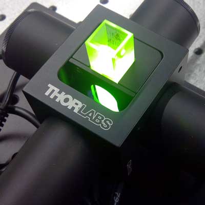
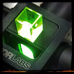
Left: Lens tubes with plano-convex lenses. Right: Cuvette in sample holder.
Specifications:
We use two High-Power LEDs in our setup, the M365L2 at 365 nm with >190 mW of power, and the M455L3 at 455 nm with 900 mW.
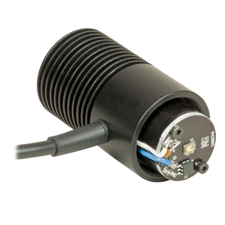
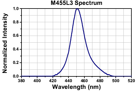
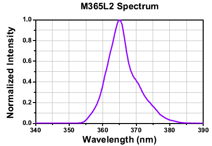
High-Power LED and spectra. Figures from Thorlabs, Inc.
Parts with Thorlabs Item numbers:
| Item Number | Item | Qty | |
| 1 | MB2020/M | Aluminum Breadboard, 200 mm x 200 mm x 12.7 mm, M6 Taps | 1 |
| 2 | CVH100/M | Cuvette Holder for Micro & Macro Cuvettes | 1 |
| 3 | M455L3 | Royal Blue (455 nm) Mounted High-Power LED, 1000 mA | 1 |
| 4 | M365L2 | UV (365 nm) Mounted High-Power LED, 700 mA | 1 |
| 5 | TPS001 | 15 V Power Supply Unit for a Single T-Cube | 2 |
| 6 | LEDD1B | T-Cube LED Driver, 1200 mA Max Drive Current | 2 |
| 7 | LA1951 | N-BK7 Plano-Convex Lens, Ø1", f = 25.4 mm, Uncoated | 2 |
| 8 | SM1L20 | SM1 Lens Tube, 2" Thread Depth | 2 |
| 9 | SM1L105 | SM1 Lens Tube, 0.5" Thread Depth | 2 |
| 10 | SM1T2 | SM1 (1.035"-40) Coupler, External Threads, 0.5" Long | 2 |
| 11 | RS1P/M | Ø25 mm Pedestal Pillar Post, M6 Taps, Length=25 mm | 1 |
| 12 | SM1CP2 | Externally SM1-Threaded End Cap | 2 |
| 13 | CF125 | Small Clamping Fork, 1.25" Counterbored Slot, Universal | 1 |
| 14 | SH6MS12 | M6 x 1.0 Stainless Steel Cap Screw, 12 mm Long, Pack of 25 | 1 |
| 15 | ME1-G01 | Ø1" Protected Aluminum Mirror, 3.2 mm Thick (optional) | 2 |
| 16 | SM1RR | SM1 Retaining Ring for Ø1" Lens Tubes and Mounts | 2 |
| 17 | SPW602 | Spanner Wrench (optional) | 1 |
Remarks:
- The SM1 Coupler (SM1T2) is used to fix the LEDs to the 2” lens tubes.
- The Plano-Convex lenses have to be mounted with the planar face towards the LED in order to reduce aberrations.
- We use cheap uncoated BK7 lenses. The transmission at 365nm is still around 90% and the optical quality is sufficient for illumination.
- The lenses are fixed with retaining rings inside the lens tubes. The distance between lens and LED is critical in order to get a collimated beam. The LA1951 lens has a back focal length of 17.7 mm (Distance between the light source (LED chip) and the planar side of the lens.) During the mounting the first retaining ring is screwed into the lens tube down to a depth of approximately 26-27mm. Then the lens is carefully inserted with the convex side towards the retaining ring. Then the second ring is used to fix the lens. The exact position of the lens inside the tube is not too critical because the lens-LED distance can be slightly varied changing the position of the LED on the SM1 Coupler. The beam diameter has to be adjusted to fill the input window of the sample holder.
- The retaining rings can be rotated in the lens tubes with a screwdriver or much safer with a spanner wrench (Thorlabs SPW602).
- We indicate the /metric /variants of the Thorlabs parts.
Variants:
- The mirrors (ME1-G01) in front of the LEDs are optional. We have more than enough power in our applications without them.
- In principle even the plano-convex lenses are optional. Without lenses the LED could be mounted with shorter lens tubes (SM1L05). However, the lenses not only increase the irradiance but also isolate the sensitive LED chip from the sample chamber.
- The power supplies could be connected to a timer unit in order to control the irradiation time.
Warnings:
- The intense UV radiation from the high power LEDs can damage you eyes.
- Make sure that the operation current of the LED Driver does not exceed the maximum allowed value of the LED. Set the LED Current Limit on the driver.
Comments or questions
Please use our blog for comments or questions. 
Licence:

Instrumentation Details by Wajih Al-Soufi is under a Creative Commons Attribution-NonCommercial-ShareAlike0 International License.